Back to it20.info
Storage Architectures for Virtualization LAST UPDATED on 22nd December 2009
1 Introduction
2 Background: Storage Management Principles in a Virtual Environment
3 High Level Design Principles for Storage Resiliency in a Virtualized Environment
3 . 1 Building Architectures
3 . 2 Campus Architectures
3 . 3 Globe Architectures
3 . 4 Hybrid Designs
3 . 5 Networking Considerations
3 . 6 SAN Considerations
3 . 7 Conclusions and Summary Table
4. Data Loss and Data Integrity in Replicated Storage Scenarios
4 . 1 Asynchronous Vs Synchronous replication
4 . 2 Data Consistency: Not Only a Technical Issue
5 High Availability and D/R at the "Virtualization layer" Vs "Virtual Machine layer"
6 Storage Resiliency: Actual Implementations in a Virtualized Environment
6 . 1 Building Implementations
6 . 2 Campus Implementations
6 . 2 . 1 Campus Implementations for VMware Virtual Infrastructures
6 . 2 . 1 . 1 Campus Implementations for VMware Virtual
Infrastructures (Host-based Replication)
6 . 2 . 1 . 2 Campus Implementations for VMware Virtual
Infrastructures (Storage-based Replication)
6 . 2 . 2 Campus Implementations for Microsoft Virtual Infrastructures
6 . 2 . 2 . 1 Campus Implementations for Microsoft Virtual Infrastructures (Host-based Replication)
6 . 2 . 2 . 2 Campus Implementations for Microsoft Virtual Infrastructures
(Storage-based Replication)
6 . 3 Globe Implementations
6 . 3 . 1 Globe Implementations for VMware Virtual Infrastructures
6 . 3 . 1 . 1 Globe Implementations for VMware Virtual
Infrastructures (Host-based Replication)
6 . 3 . 1 . 2 Globe Implementations for VMware Virtual
Infrastructures (Storage-based Replication)
6 . 3 . 2 Globe Implementations for Microsoft Virtual Infrastructures
6 . 3 . 2 . 1 Globe Implementations for Microsoft Virtual Infrastructures (Host-based Replication)
6 . 3 . 2 . 2 Globe Implementations for Microsoft Virtual Infrastructures
(Storage-based Replication)
6 . 4 Conclusions and Summary Table
1. Introduction
This document is a summary of the various storage architectures commonly seen in virtualization deployments. Virtualization has morphed very quickly from being a server technology (i.e. which allows sysadmin to carve out more than one OS per physical server) into being a datacenter technology that can't do without a proper storage setup in order to fully exploit all its potential. The fact of the matter is that there is at the moment more potential to exploit (and more confusion) around storage architectures for virtualized environments than there is for server environments. I am not simply talking about storage virtualization; I am rather talking about storage architectures designed to support server virtualization (this might or might not include storage virtualization).
The document outlines high level considerations and will immediately set the stage for the terminology being used (sure there is a standard terminology but, as a colleague of mine used to say, the good thing about standards is that there are many of them). After that we will get into how the various technologies map into the high level design principles we have outlined. This is the tough part: we will try to mix and match various storage technologies with various server virtualization technologies, with various tools and utilities. The combination of all this will determine what you can do and what you can't do.
This document is oriented towards open and distributed infrastructures and specifically towards x86 virtualization environments. The document is also more oriented towards resiliency of the server and storage infrastructure rather than other important aspects (such as performance for example). I will not cover Backup strategies in this release.
It is not my intent to push a specific technology. The idea is to provide a framework of architectures (with advantages, disadvantages and more generally characteristics for each of them) with technology examples. You can use this document (and the example) as a "benchmark" for your solution / vendor of choice. Last but not least, as this is more of a "notes from the field" document, please understand that I will be adding/removing/adjusting stuff that, in the long run, may result in a slightly less structured layout. I don't honestly have time to re-read everything so that the flaw when you read is consistent. I'll pay attention though in that the content is consistent. Feedbacks (massimo@it20.info) on the content are always more than welcome.
2. Background: Storage Management Principles in a Virtual Environment
As a background, you at least need to understand how storage management works in a virtualized context. If you are familiar and experienced with products such as VMware ESX and/or Microsoft Hyper-V, you can skip this section. One of the first steps to setup a virtualized infrastructure is to assign a storage repository to one or more physical servers equipped with a hypervisor. This storage repository is typically one or more LUNs coming from a storage server. At this point the administrator has two choices: the first one is to let the hypervisor manage the disk space with its own file system and carve out minidisk files on this file system; these minidisks are going to be assigned to the virtual machines (and in turns to the Guest Operating Systems). The second choice is to assign directly to the virtual machine(s) the RAW LUN(s) that is presented by the storage server.
In VMware terms this means you can create a VMFS file system (VMware proprietary cluster file system) and then create VMDK files to be assigned to virtual machines; alternatively you can assign, directly to the virtual machines, the so called RDM or Raw Device Mappings (which are essentially RAW LUNs that are assigned to the Guest without any intervention from the hypervisor).
In Microsoft terms this means you can create an NTFS file system (yes the Microsoft hypervisor uses the same standard Microsoft file system) and then create VHD files to be assigned to virtual machines; alternatively you can assign, directly to the virtual machines, the so called Physical Hard Disk or Linked Disk (which is a pass-through to the LUN similar to the VMware RDM).
Consider that Microsoft introduced in R2 a "clustered file system" functionality called CSV (Cluster Shared Volumes). Also IT purists would tend not to call VMFS and CSV clustered file systems as they lack some of the scalability functionalities typical of such technologies. For the purpose of this document however, we will refer to them as such simply meaning that multiple hosts can access the same LUN at the same time to store virtual machines instantiated on different servers.
This picture should clarify these concepts:
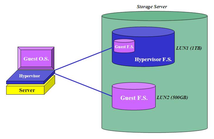
In this example the storage administrator assigned two LUNs to the physical host. The server administrator created a hypervisor file system on the first LUN (1TB) but left the second LUN (500GB) "unmanaged" from a hypervisor perspective. The administrator then created a virtual machine to which he/she attached a minidisk file (of a size close to 200GB) coming from the "managed" LUN; additionally he/she attached directly the 500GB LUN. It is important to notice that, from a Guest OS perspective, there is no difference. Assuming you were going to run Windows in that VM, the Windows setup routines would detect two hard disks attached to the (virtual) hardware that are respectively 200GB and 500GB in size.
It goes without saying that this encapsulation capability is one of the most important advantages in virtual environments since it allows a much easier manipulation compared to what you could do with RAW LUNs. Minidisks, at the end of the day, are basically big files and you can do with them (almost) everything you would normally do with files (from a backup / resiliency perspective for example). There is also built-in efficiency into this minidisk model where you can decouple the "size and shape" of the LUNs assigned by the storage administrator and assign to your VMs what you need and when you need it. In a RAW LUNs context you always have to go back and forth to the storage administrators and have them size ad-hoc LUNs for your specific guests when you need to instantiate them (granted some technologies might masquerade this back and forth process).
These are some of the reasons for which the majority of virtual deployments standardize on using minidisks Vs RAW LUNs. There are some scenarios where RAW LUNs might be required though: if, for a given virtual machine, you need to assign a disk that exceeds the maximum size of the hypervisor file system (VMware VMFS has a 2TB limit) then you have to go with RAW LUNs. Other niche scenarios where you have to use RAW LUNs include failover cluster scenarios of guest operating systems (such as MS Failover Clustering) across different physical servers. Note this only applies to VMware virtual infrastructures since MS only supports Failover Cluster configurations inside the guests using iSCSI disks connected directly to the Hyper-V guests themselves.
There is a common misconception that RAW LUNs provide a whole lot more performance (please define "performance") compared to the minidisk scenario because you "by pass the virtualization layer". The reality is that the performance gain is minimal (usually in the range of 1-5%) and certainly not enough to off-set all the advantages that I discussed above. This is due to the fact that you are not by passing the virtualization layer at all, given that most of the virtualization I/O overhead comes from trespassing the hypervisor and this happens regardless you are using a RAW access or a managed access via the hypervisor file system.
This discussion doesn't take into account the NAS scenario (which is an option for VMware infrastructure only) where the file system is created and managed inside the Storage device and not at the Host level.
3. High Level Design Principles for Storage Resiliency in a Virtualized Environment
Before we talk about actual implementations, let's discuss the design principles that should drive us through the technology discussion. We will start from defining the objective of what we want to achieve in terms of resiliency of our server and, specifically, the resiliency of the storage infrastructure. There are three fundamental high level architecture that we will discuss here. They are the Building, Campus and Globe scenarios.
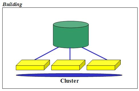
3 . 1 Building Architecture
We could actually refer to this as the most common storage architecture for virtualization. We could even call this Rack since it's commonly deployed in a single rack (inside the "building"). Simply put it's a single shared storage architecture that is available to a cluster of virtualized servers. As shared storage is becoming more like a must-have for virtual deployments, rather than a nice-to-have, this has become the blueprint architecture for the vast majority of the virtualization deployments: cluster nodes are basically stateless (i.e. with just the bare metal hypervisor with limited local configuration options) and all the assets of the organization are stored on the SAN (that is, in the storage server connected to the SAN) in the form of virtual machines and virtual hard disks: this includes the Guest OSes, the Applications code, the VM configuration information, and, more importantly, the data.
This setup has a fundamental characteristic: while the servers are loosely coupled and so very redundant by nature, the storage server is not. While the storage server might have redundant controllers the fact is that they are tightly coupled. Most of the time they are not only tightly coupled from a logical perspective (i.e. one single storage server with 2 integrated controllers) which makes some maintenance operations and potential issues more risky than having two independent storage servers, but often they are tightly coupled from a physical perspective meaning the multiple controllers come packaged into a single physical box. If this happens you can't separate the two controllers and install them into different racks or different buildings in your campus to be able to support a problem that goes beyond the standard single component failure (a controller for example).
Because of the above many people still tend to see the single (yet fully redundant) storage server in the building scenario, as a single point of failure when it comes to resiliency. That's why this solution is commonly perceived as redundant from a server perspective but not redundant from a storage perspective. Again, the storage redundancy here is not referred to the single component failure (for which you would be covered as all components are redundant) but it's referred to critical issues that might occur within the box (i.e. concurrent firmware upgrades issues or limitations, multiple disks failures, loss of power in the building etc etc).
3 . 2 Campus Architecture
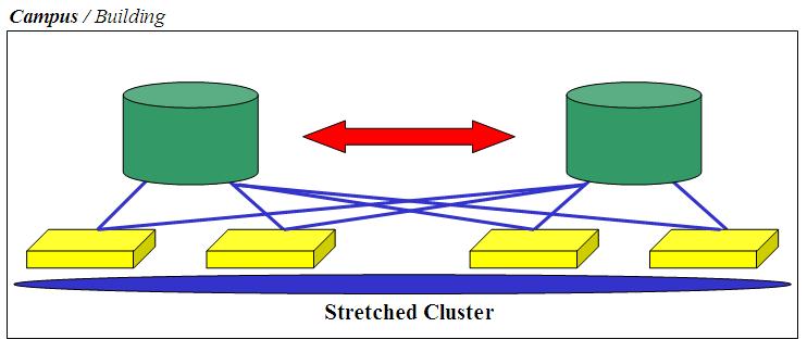
I have discussed the limitations of what I refer to as the Building solution. This solution (which I am going to refer to as Campus) is intended to overcome those limitations - obviously nothing is free so expect this to be more expensive in terms of money and complexity you need to deal with. Note that, in the picture, I have named it Campus in bold but I left the Building option simply because you might not be so much concerned about a problem at the building level but you might be concerned about the single storage deployment. In fact nothing would stop you from deploying all this into a single building (or even a single rack). I have named it Campus for the sole reason that, most commonly, customers would want the two infrastructure silos (one silo = one storage server and half the x86 servers) to be in different locations (within a certain distance). This solution is commonly associated to the notion of stretched clusters: servers are managed as a single entity (i.e. cluster) but they are physically distributed across the Campus. While you can take this approach in the first solution we discussed (Building) as well, the fact that you only have a single storage makes distributing servers across your sites a bit useless (the storage server remains a single point of failure). The most important characteristic of this solution is that disk access occurs simultaneously on both storage servers which are a mirror of each other.
By the way many would refer to this solution as Business Continuity (or Continuous Availability) although you know that these terms have a different meaning depending on who you talk to. I prefer, throughout this document, to describe the business objective and the actual implementation (details and constraint). The name you attach to any model is not important to me as long as it is consistent with your own company naming convention.
The Campus solution is typically associated to the following business targets:
Failover at all levels (servers and storage) is typically automatic: this is in fact a stretched cluster with redundant storage. The RTO is a function of how long the applications take to restart on the surviving elements.
The storage is replicated synchronously (replica might occur at the storage level or at the server level). The so called RPO is 0 in this solution
While implementations might vary based on the products used, in order to achieve the desired outcome there are two technical requirements that need to be addressed as a must-have:
All servers (across sites) need to be on the same layer 2 LAN/VLAN. This will ensure fully transparent switch over of the applications from one site to another within the Campus.
All servers in the Campus need to access both storage arrays (exceptions may apply but this is a good rule of thumb).
The uniform storage access is the most stringent of the requirements as it will drive the maximum distance of the solution. Before getting into the products that implement this, there are a couple of additional rules of thumb to consider. First of all it goes without saying that the farther the distance the higher the latency. And you can't really go beyond a certain latency level otherwise your hosts will start "screaming" against the storage. You can certainly alleviate the problem by implementing technologies that lower the latency and in this case the rule of thumb is obvious: the more you spend, the better it gets (BAU - Business As Usual). This is where typically the distance limitation kicks in: implementing this architecture within a few hundred meters is not usually a big deal but trying to stretch it to a few kilometers might become a challenge (or might become VERY expensive - depending on how you want to look at the matter).
Having this said of all the 3 scenarios (Building, Campus, Globe) the Campus one is certainly the most difficult to implement given the high end-user expectations (in terms of RTO and RPO) and integration difficulties between the various technology layers (primarily between the storage and the virtualization software running on the servers).
It is important to underline that this document is very technology oriented and not so much process oriented. This means that, while from a process and compliance perspective there might be a big difference between storage devices located in nearby buildings and storage devices located within a metropolitan area network, from a technology perspective there isn't so much difference as long as you can guarantee the transparency from a SAN and Network perspective (see the SAN Considerations and Networking Considerations sections). This is to warn you that you might find other documents that make a difference between a Campus implementation and a Metropolitan implementation. While there are indeed differences in the two implementations (especially in terms of the disasters they might be able to address), there is not a big technology difference provided the note above.
3 . 3 Globe Architecture
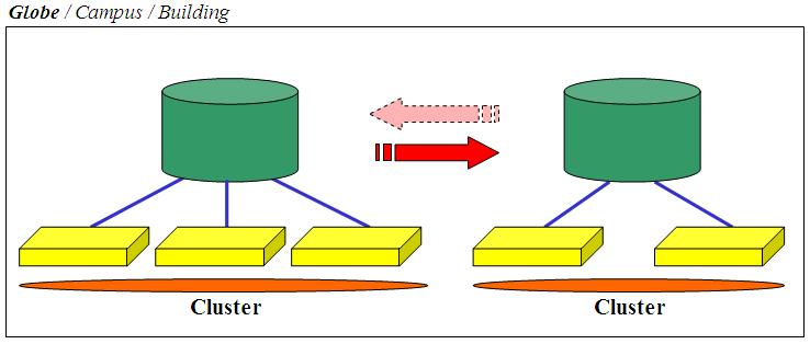
This is the third and last high-level scenario. I think it would be fair to describe this as a Disaster/Recovery solution and many - if not all - would agree with the definition. As you might depict from the picture it's similar to the Campus solution as it involves the usage of 2 storage servers but it is radically different in what you would expect it to deliver. In a nutshell this is not to be intended as a fully automated solution that automatically reacts in the case of a sudden crash of a site (or of a storage server).
Ironically, as you will note hereafter, the Globe solution is somewhat easier (easier doesn't always mean cheaper) to implement than the Campus solution. In fact you will see that there are many fewer requirements and prerequisites than the Campus setup. Similarly to the other solutions, while this one is specifically oriented and suited for long distances D/R scenarios, there is nothing that stops you from implementing these recovery algorithms at the Campus or even at the Building levels. In fact there are some situations where the Campus scenario (as described above) is either impossible or very difficult to achieve from a technical (and cost) perspective, that some customers have defaulted to technologies better suited for long distance DR type of requirements to implement them at the Campus (or even at the Building) level.
What I refer to here as the Globe solution is typically associated to the following business targets:
Because of the above the technical requirements are less stringent than the Campus solution:
It is important to understand, and this is a big source of confusion in the industry, that a D/R solution is not meant to ensure automatic recovery of a service/workload (or multiple services/workloads) should a non-redundant component of my production infrastructure fail. That's what a Building or a Campus solution is meant to do. D/R is in fact more than just an IT term: it's a set of processes (along with technologies) that allows an organization to recover, in a fully controlled way with limited automation, from a catastrophic event such as terrorist attacks or a natural disaster.
D/R is not the kind of thing that... you wake up one day and you find out that all your VMs are running in the Minneapolis data center (failed over automatically from the production site in New York) just because you lost power to a control unit. D/R is that kind of thing that potentially forces you in meetings for hours if not days to decide whether or not you should failover to the remote site. I have seen customers implementing D/R plans that took into account to remain off-line a few days without even considering a failover as it was determined that being (partially) out of business for a few days would have had less implications than a failover (with all the logical and physical consequences) would have had. This is obviously an extreme case but it should give you an idea about what D/R really is. Smaller organizations may have a faster reaction though.
As a matter of fact these are the operational characteristics (i.e. manual restart, independent clusters) based on which you would define a solution to be a Globe type of solution. While we have stated that usually Globe scenarios are associated to Asynchronous and/or Snapshot storage replication, this is not what defines a Globe solution. The replication mechanism pertains more to the integrity of the data rather than to the scenario overall. There are indeed technologies that are able to support Synchronous replication at a distance greater than 100Km but this doesn't automatically mean that you are in a Campus type of scenario. Always Remember that the replication mechanism (alone) is not what characterizes a Globe solution. While a Campus solution is pretty fixed in terms of requirements a Globe solution is typically more flexible in how you implement it. In fact the RPO in a Globe scenario might vary between 0 and 24 hours, depending on your need (and the amount of money you may spend).
3 . 4 Hybrid Designs
There are many situations - specifically in the Enterprise organizations - to have multiple redundancy levels for their infrastructures. This is where hybrid scenarios can be used. A typical example of this is an organization that would benefit from adopting a Campus-like solution with the highest levels of SLAs (RPO = 0, RTO close to 0) for their main datacenter - which might encompass more buildings in a single metropolitan area as well as a solution at the Globe level for the most disruptive and catastrophic events. The picture below describes this example:
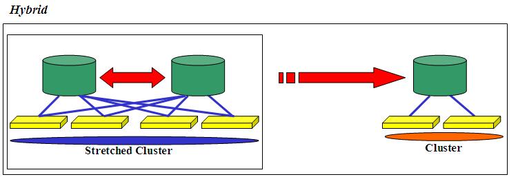
Again, the Globe scenario is usually associated with an Asynchronous replication but there might be situations where you may want/need both the Campus and the remote DR site to be strictly aligned with RPO = 0.
3 . 5 Networking Considerations
This document focuses on storage architectures but it is important to spend a few words on the networking implications as well. I think this concept should be pretty clear at this point but let's set the stage again: while networking connectivity might not be a problem for the Building and Campus scenarios, it might be an issue in Globe scenarios. As we pointed out for Building and Campus scenarios one of the requirements is that all hosts share a common Layer 2 LAN. This doesn't obviously mean that each host can only have one NIC: this means that a given network connection on a single server is Layer-2-connected to the same connection on all remaining servers in the cluster. Example: the NIC(s) dedicated to virtual environments needs to be on the same Layer 2 network across all physical servers in the cluster. This is what allows you to failover transparently any workload on any server on the (stretched) cluster. If this requirement is not satisfied you are automatically in the Globe type scenario because, as we said, Layer 2 connectivity is a must-have for Building and Campus scenarios.
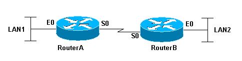
Now this is when all starts to get a bit tricky. Ideally, it would be difficult to span Layer 2 networks across the globe for a common IP addressing schema. Having this said this is well possible using the latest technologies available (note: possible doesn't necessarily mean easy). There are some networking technologies and particularly networking configurations that allow what's referred to as transparent bridging across otherwise routed networks (Layer 3). So for example, routers that connect different networks could be made to work in a way so that they transparently bridge LAN1 and LAN2 (see picture). If this happens, even assuming LAN1 is in New York City and LAN2 is in Minneapolis, if you take a host (or a VM) with a fixed IP address you can move it from LAN1 to LAN2 and viceversa regardless. This Cisco Technote might be a starting point if you are interested.
If you are in this situation then the Globe scenario becomes easier to implement as the server administrator doesn't need to bother with the different IP schema for the VMs being failed over to the remote site. There are obviously other challenges but re-IPing is certainly one of the toughest (if not the toughest) things to deal with in a global failover.
If you are NOT in this situation than the Globe scenario might become a bit more problematic. You, as the server administrator, have to also take into consideration the right mechanisms and procedures to migrate the current IP schema associated to the VMs in the production site to the new IP schema that is available in the remote D/R location. This is because, in this case, Router A and Router B don't bridge but they actually route - Layer 3 - traffic from LAN1 (which is on a given IP network) to LAN2 (which is on a different IP network). This isn't a common task at all since, other than the challenges and risks associated to re-IPing all VMs at failover time, it might have other implications at the application level: in fact there might be some applications that are "sensitive" to IP addresses changes.
Because of this some customers I have been working with decided to take a third approach. Instead of creating this stretched network configuration (which was impractical for them) and instead of having to re-IP all VMs (big nightmare)... they decided to reconfigure the whole network infrastructure at disaster-time. During normal operations LAN1 and LAN2 would be on different network schemas but, if a disaster occurs, the networking equipment at the D/R location would get reconfigured with a backup of the networking configuration of the production site. In that case VMs could be restarted on the remote location without the server admin having to change anything in the VMs configuration. Similarly the networking administrators didn't have to bother with the complexity of building a stretched LAN across the two sites using the bridging technology we have referred to.
The net of this is that there is no free lunch. There is complexity associated to this global networking configuration and it needs to be solved somehow: whether it is the server administration that solves it (reconfiguring the IP of the workloads) or it's the networking administrator (either using the stretched Layer 2 configuration or through a networking reconfiguration at disaster-time) you have to plan for it.
3 . 6 SAN Considerations
Similarly to the network considerations above, SAN design is not the ultimate goal for this document but yet it is important to set the stage properly. Someone might have depicted at this point that the major difference between a Campus and a Globe solution is the architecture that describes the way storage is accessed. Simply put, if my SAN characteristics are good enough so that any server can access any storage then I am in a Campus like scenario. Alternatively if storage access attributes (latency and bandwidth) vary depending on the location then I am more likely in a Globe type of solution. The interesting thing is that while distance plays a big role, it's not the only discriminator factor: in fact, depending on the budget I have, I could create a 10Km connection between two sites which would result "transparent" to the server and storage infrastructure (i.e. logically one single physical site) or I could create a 2 Km connection between two sites which would look like two distinct and different regions from a bandwidth and latency perspective. You might wonder where the trick is. Well the trick is the money (as usual) where the cost to implement the former is order of magnitude higher than the cost to implement the latter. So don't be surprised if you ever bump into Campus like scenarios where the two sites are 10Km apart and/or Globe scenarios where the two sites are just a 2 or 3 Km apart. Remember: the distance is only one aspect of the limitation.... with the right amount of money you can buy (almost) anything in this world.
While the SAN purists may kill me for the following oversimplification, let's assume there are fundamentally 3 different methods to "extend" a SAN.
The first method is to simply use longer FC cables that might allow to stretch a fabric across two buildings. We are talking about a distance of 300 / 500 m depending on the speed you want to use (1Gb/s vs 2Gb/s vs 4Gb/s). In this case it's the end-user that is responsible to deploy and cable properly the infrastructure.
The second method is using so called Dark Fibers / DWDM. In this case you wouldn't be deploying cables but you would actually rent an already deployed cable (or a fraction of it). While this solution might provide the transparency described in the paragraph above it does have an associated cost which might be prohibitive for many customers. More commonly this is a technology used for Campus type scenarios with sites dispersed at the metropolitan level.
The third method available is using Multi Protocol Routers that are able to encapsulate the FC traffic into IP frames. This way you can stretch your fabric across much longer distances (leveraging IP WANs) at a much lower cost compared to Dark Fibers. Obviously the usage of FCIP (Fibre Channel over IP) techniques have implications in terms of bandwidth and latency (specifically latency) that make it unsuitable for Campus like scenarios (even at short distances). The good thing is that the limit is the globe in terms of how disperse the sites can be.
3 . 7 Conclusions and Summary Table
In summary we have outlined the three high level design principles commonly used for designing resilient storage infrastructures in virtual environments. What I have referred to as Building doesn't have any sort of resiliency from a storage perspective (yet it's one of the most common setup in virtual environments). The Building setup might be expanded and complemented with other components to create what I have referred to as Campus and Globe architectures. It would be reasonable to describe the Campus scenario as a tightly integrated infrastructure (within a certain distance) with which you can achieve the best levels of resiliency, automation and RPO. On the other hand the Globe scenario might be described as a loosely integrated infrastructure (with an RPO that is typically and necessarily > 0) with which you can create a resiliency plan at the globe level without distance limitations.
The other thing is that while the Campus scenario is pretty well defined in terms of requirements and service level delivered, the Globe scenario might be implemented in many different ways as you can depict from the table below. As an example you can create a Globe implementation using a cheap third party replica tool to bring snapshots of your VMs taken overnight to a remote location where you would bring up manually your VMs after a disaster. Or alternatively you can create a Globe implementation using expensive native storage replication with enterprise tools for semi-automatic VMs recovery.
This table is a simplified summary of the 3 scenarios we have described in this high level design section. What you can actually achieve also depends on the technology you use to implement these models. The table contains average values and comments based on common implementation scenarios.
The take away from this table is that there is no free lunch. If your major concern is data consistency you have to compromise with distance and/or performance (disk latency). If you major concern is distance and/or performance (disk latency) then you have to compromise with data consistency.
| Building | Campus | Globe | |
| Typical Cost | Cheap | Expensive | It Varies (from Cheap to Very Expensive) |
| Implementation Effort | Easy | Very Difficult | It Varies (from Easy to Very Difficult) |
| Typical Distance Between Storage Servers | (Not Applicable - Single Storage) | Hundreds Meters / Few Kilometers (100) | Unlimited |
| Typical RPO on Storage Failure | (Not Applicable - Single Storage) | RPO = 0 | RPO = 0 / Milliseconds / Seconds / Minutes / Hours |
| Typical RTO on Storage Failure | (Not Applicable - Single Storage) | RTO = 0 / Seconds / Minutes | RTO = Hours / Days |
| Typical Storage Configuration | All Servers See the Single Storage | All Servers see All Storage (Even Across Sites) | Servers in Site See Storage in Site (Not Across Sites) |
| Typical Network Configuration | Layer 2 | Layer 2 | Layer 2 / Layer 3 |
| Typical Servers Configuration | Single Cluster | Single Cluster (Stretched) | One Cluster per Site |
| Can Survive a Single Storage Controller Crash | Yes | Yes | Yes |
| Can Survive Dual Storage Controllers Crash | No | Yes | Yes |
| Automatic Recovery on Storage Failure | No | Yes | No (requires manual steps) |
| Automatic Recovery on Building Failure | No | Yes (ideally) | No (requires manual steps) |
4. Data Loss and Data Integrity in Replicated Storage Scenarios
This topic is so important that it deserves a section for itself. As many of you understand there is a fundamental difference between Data Loss and Data Integrity in a recovery scenario. To make a very complex matter short, Data Loss means you have actually lost data, whereas Data Integrity issues mean you have the data, but they are inconsistent. Most people would lead to think (and I agree) that Data Integrity issues are way more important than Data Loss issues. Especially if the lost of data is consistent across all systems in your infrastructure (if it's not consistent it would be a data integrity issue).
Data Loss might be (yet marginally) associated to Campus like scenarios where you have two storage servers that are always kept in sync (no matter what the technology is). The loss might come from non committed transactions onto your storage devices. Think for example a scenario where a building in a Campus collapses and all servers active in that building need to restart the applications (and the virtual machines wrapping the applications) on the servers in the other building. In that case the virtual machines would start in a so called "crash consistency" (called this way because the status is similar to that of a physical server with local data disks that experienced a power failure). Most modern operating systems and applications can recover easily from such a situation; obviously the OS and the Application will restart w/o all the stuff that was left in memory and not committed to disk (this is where the Data Loss part is). This isn't usually a problem: think for example how a database works. Transactions get executed on the server and committed. If a transaction is committed it means it has been physically written onto the database log files and, as such, can be recovered. Ironically the transaction might have been written to the log but not yet written into the database (but rather just kept in memory). If a server crashes the database engine will restart the database applying all transactions that have been written onto the logs so bringing it to a consistent state. Other applications with a recovery procedure that is not as sophisticated as that of the most popular RDBMS might suffer from a slightly larger loss but the key point is that most applications would be able to recover to a specific consistent state. Usually for Campus type scenarios Data Loss (i.e. RPO) is intended and assumed to be 0 other than this philosophical discussion. As a matter of fact this wouldn't even be considered Data Loss at all given all committed transactions are there and you have only lost what's actually still "up in the air" so to speak.
Globe type of scenarios might be different though. Very different. For example there might scenarios where an organization can decide to implement a DR plan based on snapshots (a snapshot can be taken and replicated at the storage level or through the software layer). In this case, assuming you are taking and replicating snapshots every 24 hours, you have a big Data Loss window (RPO=24hours). The worst case scenario is that you may lose 24 hours worth of data and transactions. Particularly challenging in this scenario is the Data Integrity issue: not only in these 24 hours you have lost a good chunk of the transactions and data but, in case those transactions have triggered other transactions and tasks that are not in your complete control (example: interacting with an external entity updating data that you don't have direct control of) you maybe at a point where your transaction doesn't exist anymore (as it got lost during the disaster) but you have other IT counterparts that assume your transaction has completed and you have it in your records. While it doesn't exactly work in this way, a good example might be a money transfer from a bank account to another. Imagine a distributed transaction occurs between two banks (A and B) where 500$ are moved from account A1 ( A1 = A1 - 500$) to account B1 ( B1 = B1 + 500$). All went well. Should a disaster occur a few minutes later at Bank A most likely you will have your transaction record lost (A1 = A1 - 500$) while Bank B still has its record in the system. While, as I said, it doesn't really work like this, it should give you an example of how Data Loss issues might turn into Data Integrity issues as well.
4 . 1 Asynchronous Vs Synchronous replication
Synchronous replication is the preferred method to use for storage synchronization in case data consistency / accuracy is mandatory. The idea is that the data needs to be physically written on both storage devices before control (and the I/O acknowledgement) can be returned to the application. Asynchronous replication has different meanings depending who you ask. For some people Asynchronous replication means that the server writes the data on its active storage device and, once the transaction is on the disk, it gives back control to the application. Instantaneously (but with an obvious slight delay) the active storage sends the update to the secondary storage ASAP. The delay is usually in terms of milliseconds / seconds (depending on the latency and bandwidth between the sites). The delay is so low that many vendors call this technique Near-Synchronous replication. There is another option that is sometimes used which is what I refer to here as Snapshots. The idea is to have a software utility (or the storage firmware) take a snapshot of the minidisk and send it over (typically via TCP/IP) to the remote site. Usually the RPO in this case is between 1 hour and 24 hours (depending on the DR policies). This technique is also referred to as Asynchronous replication by the same vendors that use the Near-Synchronous replication term. Make sure you check with your storage vendors and agree on the terms being used in the discussion. The following table summarizes the characteristics of the two approaches.
| Synchronous | Asynchronous | Snapshot | |
| Also Referred To As (by some HW vendors) | Synchronous | Near-Synchronous | Asynchronous |
| Typical Scenario | Campus | Globe | Globe |
| Typical Distance | 500m / 10 Km (up to 100+Km but with HIGH costs) | Unlimited | Unlimited |
| Requires a Stretched SAN | Yes (Dark Fiber / DWDM) | Yes (Dark Fiber / DWDM / FCIP) | No (replica is typically via IP) |
| RPO characteristics | RPO = 0 | RPO > 0 (ms / seconds / minutes) | RPO >> 0 (minutes / hours) |
4 . 2 Data Consistency: Not Only a Technical Issue
It's important to call this out. While this document is very focused on the technology aspects of the High Availability and DR concepts related to the storage subsystem in a virtualized environment, the actual implementation has to include important additional aspects such as the organization internal processes. Technology is just one little aspect that allows a company to restart its business operations should a complete disaster hit its headquarters. As you might depict this is more important in a DR (i.e. Globe - long distance) type of scenarios where the organization is facing with multiple issues. The operations that need to be put in place to restart the business is one aspect, but there are other aspects such as the quality and the alignment of the data so that they are not just consistent from a technical perspective but they are consistent from a business-view perspective. Technology can only go so far. There is no single technology (or a mix of them) that could automagically solve all DR associated problems w/o proper planning and operational procedures.
5. High Availability and D/R at the "Virtualization
layer" Vs "Virtual Machine layer"
This document has a somewhat limited scope. It will not, in fact, discuss storage HA and DR techniques that can transparently be implemented within guest Operating Systems running on top of the hypervisor (as if they were physical systems). Throughout the document, and specifically when talking about the actual products implementations, I will not take into account solutions that could either be implemented on physical servers running Windows / Linux or within virtual machines running the same base software. Basically I am not taking into account solutions that can be implemented within a guest simply because a partition can mimic the operation of a physical server (which, in retrospect, was the initial value of virtualization). Typical examples are some Lotus Domino or MS Exchange clustering options that could get away with shared storage scenarios and have replication mechanisms that can keep different mail servers aligned by means of native application replicas. Similarly, other topologies I am not covering in this document, are all those solutions that - independently from the applications - are able to interact at the Guest OS level and provide remote data copies as well as optional automatic restarts. This would fall into the same category I have described above which is: a software that has been designed to work on physical servers running Windows / Linux and that happens to run similarly on Guest Operating Systems running on top of a given hypervisor.
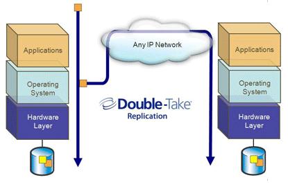
A good example of this solution is Double-Take for Windows which is a host level storage and server high availability solution that is able to keep one or more Windows servers in sync through IP data replication and have built-in high availability features to restart services and applications should a system fail.
As you can depict from the picture, if you install this software stack into a couple of Windows Guests running on your hypervisor of choice nothing really changes. The biggest thing is that you no longer leverage a physical box (the "Hardware Layer" blue brick in the picture) but you would rather use a dedicated partition running the same software.
While it's perfectly feasible to use such a scenario in a virtualized environment, I truly believe that this sort of infrastructure services should be provided at the basic infrastructure level rather than being leveraged within each of the guests. I have made a similar point months ago when talking about the nature and the architecture of server high availability solutions in a Building type of environment. You can read that article here. The same concept can be applied to the storage high availability issues for both Campus and Globe scenarios. While moving these infrastructure services at the virtualization layer might sound more complicated than mimic in the Guest what you could do on physical servers, it does have a strategic value associated to it. Think, for example, of a scenario where you have 100 OS guests supporting 100 heterogeneous applications running on 10 physical hosts (a conservative 1 : 10 consolidation ratio and a realistic 1:1 application/OS ratio are assumed). Should you implement a traditional Double-Take solution at the guest OS level, most likely you would end up creating 100 clusters to protect 100 applications across 200 partitions (2 VMs per cluster). If, on the other hand, you move the high availability and replication algorithms at the virtual infrastructure level you keep the 100 partitions unaltered and you only enable the HA and disk syncing functionalities on a single 10 hosts cluster (i.e. the physical boxes that comprises the virtual infrastructure). Perhaps it is for this very reason that Double-Take came out with newer versions of their solution to address specifically this scenario. The products are called Double-Take for Hyper-V and Double-Take for VMware Infrastructure: they essentially do what's described in the picture above with the only "slight" difference that they treat the hypervisor as the host OS, essentially targeting a step below in the entire stack.
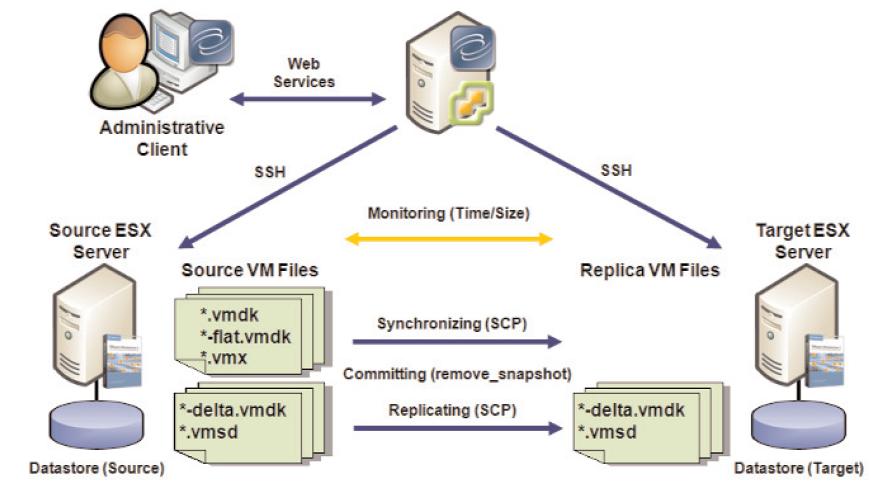
For convenience, the picture shows the architecture for the VMware Infrastructure version. Note that, in this case, the Double-Take product is deployed as an external component (due to the fact that VMware doesn't encourage ISVs to develop code against the local ConsoleOS, and in the case of ESXi it would be even more challenging). For Hyper-V the layout might be different in the sense that Double-Take would be installed on the local servers (in the parent partition). As you can guess from the picture, Double-Take works with the minidisk files (vmdk files in ESX language) without bothering what's actually installed and what actually runs inside those images.
I have used Double-Take as a mere example. More information about the tools and specific technologies used to accomplish the goal will follow in the implementation sections.
I want to stress again that it might make perfect sense - in some circumstances - to implement a partition-based HA / replication strategy. Having this said I strongly recommend readers to valuate a longer term plan (with all benefits associated) where the infrastructure functionalities are delivered at the virtualization layer and not within the Guest OS. This is the scenario that this document covers anyway.
6. Storage Resiliency: Actual Implementations in a Virtualized Environment
In this section I want to take the high-level design principles I have mentioned and apply them to specific products and technologies. This is a multiple dimensions effort. One of the dimensions is the Virtualization software being used: a given product may or may not implement (properly) a given architecture or a design principle. This is what I'd like to discuss in this section and I will take into account the leading vendors that are playing a key role in the virtualization space.
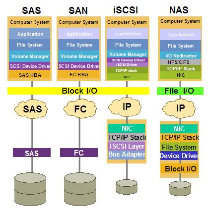
Another dimension is the storage protocol. I am going to focus on the 4 protocols I have outlined in the picture. The protocol used to connect the hosts to the (shared) storage might play a key role in what you can actually implement and how you can do that.
There are another couple of reasons for which I am showing this picture. The first one is to call out that while the iSCSI, NAS and FC might vary in how you can implement the HA and D/R scenarios we have discussed, SAS (Serial Attached SCSI) is not going to be much different than FC. Despite this, right now SAS connectivity is mostly positioned as entry level so most likely found in the Building scenario (where storage HA and D/R is not even considered). So expect to see most of the discussions around the three big protocols iSCSI / NAS / FC as far as redundant storage scenarios are concerned.
The second reason for which I am showing this picture is because we need to keep in mind the characteristics of each protocol. While the NAS protocol for example might provide some level of flexibility in certain HA and D/R scenarios we need to understand that it does have some limitations in the way it interacts with the servers in a complex enterprise environment. First of all it is a File I/O protocol (i.e. you don't share raw storage but a file system someone has already created for you in the back), and secondly it is based on IP connectivity. This is not to bash the NAS protocol or any other IP based protocol (i.e. iSCSI) but it's just to make clear that organizations might decide to choose a FC SAN (for its robustness, for its scalability etc etc) even though it doesn't always score as the most flexible or cheapest architecture for HA and D/R scenarios. Having this said iSCSI and NAS have, and will continue to have, an important role when it comes to supporting virtual infrastructures at many organizations.
As a reminder, please keep in mind that while most of the implementation details I will discuss hereafter have been successfully implemented in the field and are generally fully supported by all vendors, there may be other implementations that are "technically possible" but are not automatically blessed and certified by the various vendors. Some vendors might also have public and general (negative) support policies and ad-hoc deviations for which they might selectively support a given implementation on a customer by customer basis. This document is intended to provide an overview of how various technologies could be tied together to achieve a certain goal. Always refer to your vendors and/or systems integrator to have their blessing in what is and is not actually officially supported.
6 . 1 Building Implementations
This is going to be a very short sub-chapter. Since the Building Architecture doesn't include any dual storage configuration there is not an HA or D/R storage implementation to describe either. Yet, as I pointed out, this is how the vast majority of the VMware and Microsoft customers out there have implemented their server farms. This configuration is the bread-and-butter of virtual environments which usually requires shared storage implementations to exploit all the potential (such as being able to move a workload from one server to another on-the-fly). Yet, if you are to implement a brand new virtualized Building type of infrastructure, you might want to implement it in an open way that allows you to expand it into a Campus or Globe type of deployment, should the need arise.
6 . 2 Campus Implementations
This is when things start to get complicated. We have already discussed the philosophies behind this scenario in the High Level Design Principles section above so we will get straight into the matter here.
6 . 2 . 1 Campus Implementations for VMware Virtual Infrastructures
Generally speaking there are two macro type of implementations that allow you to achieve the Campus scenario for VMware infrastructures (in theory - see below). The first one is Host-based and the second one is Storage-based.
6 . 2 . 1 . 1 Campus Implementations for VMware Virtual Infrastructures (Host-based Replication)
This is the most classical method to implement Campus high availability for Storage (and Servers). If you remember the characteristics discussed above for this scenario, we have stated that both storage devices need to be accessible from all servers in the (stretched) cluster. HA for the servers is guaranteed through standard server clustering technologies (VMware HA in this case) whereas storage HA would need to be addressed by a volume manager running at the host level that writes disk transactions on both storage devices simultaneously.
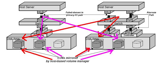
This picture (courtesy of Veritas) visualizes this concept. Hosts see both Disk Arrays (aka storage servers) and hosts are able to commit disk writes on both of them. This is a typical scenario in standard cluster environments where a Storage High Availability concept is required as well. In non-virtualized environment the portion of the storage device that the host can mirror would typically be the shared Data LUN. Obviously only the active host owning that LUN might be able to twin-tail and keep the storage aligned. As you can see in the picture on the left I have imagined an Active/Active configuration where the first host in the cluster would "own" two LUNs coming from the two disk arrays and the second host in the cluster would "own" two other different LUNs. Should one of the two hosts fail, the server high availability piece would failover the workload from one host to another, allowing the surviving host to manage all four LUNs (as 2 pairs of mirror) and both workloads.
The same picture also shows the benefit of having multiple paths to get to the storage device (we'll take that for granted and it's not the core of our discussion). Veritas has built (a large portion of) its fortune with these technologies. Specifically this technology is called Veritas Volume Manager.
There is no way, as of the time of the first vSphere release, to implement a host-based synchronization across two independent storage devices. In other words vSphere doesn't yet allow native mirroring of VMFS volumes across different Storage devices. Note that there are customers implementing software mirroring within the virtual machine OS though, but this is beyond the scope of this document as it's not a hypervisor-delivered feature. There have been speculations in the past that VMware would have been able to provide a functionality to ESX administrator to basically do mirroring across two different VMFS volumes. And since the two VMFS volumes could potentially come from two different disk arrays, they would automatically provide a host-based replication technology out-of-the-box. While I am sure there are still plenty of discussions inside VMware about this (and the priority to assign to such a feature) today we don't have it available. To make things worse the fundamental architecture of VMFS (but specifically the fundamental trend/suggestion to not load anything inside the ESX host - ESXi being the extreme example where it's not even basically possible to load third party code) makes it impossible for technology partners to develop a volume manager that extend the default VMware volume manager. This is the main reason for which a Veritas Volume Manager for ESX doesn't exist - as of today at least.
It is important to understand that, in this scenario, the two storage devices would not need any sort of replication support. It is in fact the host, which has visibility to both disk arrays at the same time, that instantiates the mirror between the LUNs associated to that host. The disk array might be the most stupid limited and cheapest JBOD you can think of.
6 . 2 . 1 . 2 Campus Implementations for VMware Virtual Infrastructures (Storage-based Replication)
So is it possible to configure a Campus type of scenario (as we described it) with VMware vSphere? Yes it is possible, you just need to off-load the job that the host is supposed to do all the way into the storage layer. This is not as simple as it sounds though.
Fibre Channel (FC)
Most of the readers at this point would be led to think that you can achieve this with the replication feature most mid-range and high-end storage devices make available. Things like IBM PPRC, EMC SRDF or Hitachi TrueCopy. Not so easy.
Remember the fundamental characteristic of the Campus scenario as we have defined it: 1) all servers can access all storage at the same time and 2) the failover (for servers and storage) is automatic. The technologies I have mentioned above are able to keep in sync an active LUN on one storage to a passive LUN into the other storage device but it is in the automation process that all falls apart. In fact should the building with the active storage in the Campus collapse there are manual recovery steps that need to occur before the virtual machines and their guest operating systems can be restarted:
The passive LUNs on the surviving storage need to be reactivated
The ESX hosts needs to be restarted or alternatively their SAN configuration needs to be refreshed (now the LUNs come from a different storage from different WWNs - never mind the data are the same).
The VMs need to be re-registered
Etc
Another critical aspect to consider is that once a failover has occurred the failback process might be painful as it will require a scheduled shutdown of the entire infrastructure to revert the replication and bring back the workloads to the primary data center. You may think of it as a scheduled DR event in a way.
It is obvious that being able to create an active / active storage relationship (i.e. half LUNs replicates "eastbound" and the other half replicates "westbound") will not solve the fundamental architectural issue we have described here. So, no, this is not what we would usually define a Campus like scenario (or a Business Continuity scenario if you will). The problem is that all these replication solutions assume two independent VMware storage domains such as a domain A replicating onto a domain B and/or viceversa (depending if the configuration is A/A or A/P). You cannot have multiple storage domains simply because the ESX cluster cannot transparently migrate a Fibre Channel connection from one domain to the other automatically (assuming a storage domain could failover automatically onto its replica - which is not usually the case). Just to make sure we are on the same page I define a VMware storage domain as a fully redundant storage device with its own standalone identity. The vast majority of the storage arrays available on the market fall under this category: IBM DS3000/4000/5000/6000/8000, IBM XIV, EMC Symmetric, HP EVA, HP XP12000 etc. So how do I make VMware look at a distributed, stretched and mirrored disk array across different locations as if it was a single storage domain that ESX can transparently deal with? I would ideally need to take one of the fully redundant products mentioned above and be able to "split" them into two different locations. That's the problem, most of the products available in the market are physically monolithic, fully redundant sure, but yet they come as a single physical device that you cannot stretch across buildings. There are obviously exceptions to this and the exceptions are the only products that would allow you to create a VMware server farm stretched in a Campus scenario. Notice that you can stretch your VMware cluster independently, the problem is how to keep a mirrored stretched copy of the data that is transparently available to the cluster.
More by chance than by design, most of the storage virtualization products available in the market do have this characteristic of being modular in nature. A few examples:
While not, strictly speaking, a storage virtualization solution, the NetApp storage servers happen to be engineered with two physically separated controllers (aka heads) that can be physically separated. This allows to achieve the desired result (i.e. stretching). Notice NetApp also supports the usage of standard storage servers as a back-end disk repository (instead of their own disk shelves). This essentially turns the NetApp Heads into front-end Gateways between the actual storage servers and the VMware hosts. In a way this is indeed storage virtualization similar to what the IBM SVC does.
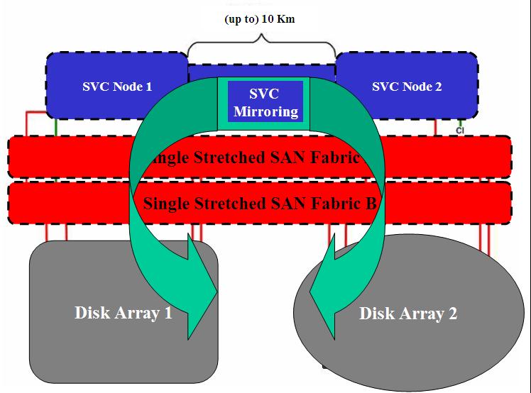
The IBM San Volume Controller (SVC) is in fact the next example; it's a storage virtualization product that comes packaged, as a minimum, as two System x servers (aka SVC appliances). Together they form the SVC cluster (think about the two servers as if they were the redundant controllers in a DS3000/4000/5000 class of devices, or two NetApp heads if you will). The big news is that you can take the servers and stretch them up to a few kilometers apart.
The Datacore SanSymphony product works in a similar way. The difference is that the two servers are standard Windows servers where you can install the Datacore product. I am not sure about the distances (which you always need to check with your vendor) but the philosophy is pretty similar: put a server in building A, a server in building B and have VMware vSphere access the storage device uniformly as if Datacore server A and server B were two controllers of a traditional storage device.
There is a big common question mark when it comes to transparently automate the recovery process in a scenario where you let the storage infrastructure stretch across sites (i.e. what we defined storage-based replication). This big question mark is the so called split brain issue. While all the solutions mentioned above can survive single and even multiple components failures, the failure of a complete site is a different thing. When this happens, the storage components at the surviving site have a big dilemma: the surviving site has typically no way to know whether the problem is due to an actual remote site failure, or it's just due to a temporary/permanent fault in the communication links between the two sites. If it's the latter and the storage servers were to assume both should be promoted as "surviving site nodes" a split brain would occur where both sites would be working separately on their own copy of the data. The problem is how you would then "merge" those data when the communication is re-established (that would be impossible). Each stretched storage solution has its unique way to solve split brain conditions: some solutions can be implemented in a way so that the decision is automatic (which is what a Campus like scenario would require - as per our description) some can be implemented in a way where this condition would stop the operations and manual tasks by an operator may be required.
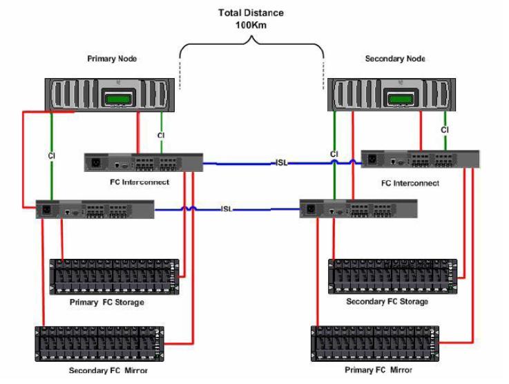
I'll start digging a bit into the NetApp solution. The best way to look at this is that Primary Node and Secondary Node are essentially the two controllers of a single storage device (i.e. what I referred to as the storage domain). Because of the modular design the two controllers can be taken apart (up to 100Km) and configured in a way so that a portion of the disks in the site on the left mirrors onto the disk in the site of the right and viceversa.
The NetApp device is an A/P device by nature where a single controller owns a set of disks at any point in time and allows the other controller to take ownership of them in case of failure. In this scenario a cross A/P configuration has been implemented so that both controllers do useful works during normal operations.
The idea is to have, on top of them, a stretched cluster of VMware ESX servers and the cluster not even noticing that it's dispersed geographically. In this case, should one of the two sites fail, VMware HA would kick in and restart the partitions on the surviving ESX servers in the cluster. The surviving ESX servers wouldn't even notice the storage issue as they would continue to work on the local copy of the data (after the NetApp heads has transparently terminated the failover).
The picture on the left outlines the physical components required to set this up.
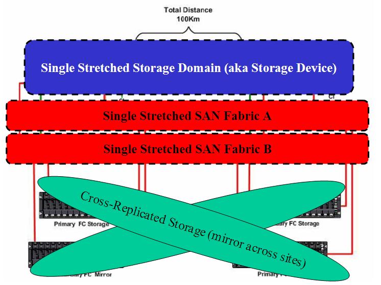
The picture on the right, on the other hand, reminds the reader of the logical design where, again, there is a single stretched storage device that encompasses both sites in the Campus scenario.
For more general information about this NetApp MetroCluster solution there is a very good document here. Specifically for VMware environments there is an even more interesting document here.
The last document does a great job at describing the what-if failure scenarios. As you will notice you can loose multiple components at the storage infrastructure level and still be resilient (and transparent) as far as the stretched VMware cluster is concerned. As you may notice, you are transparently covered in all combination of failure scenarios but the Building/Site failure; this scenario requires manual intervention due to the split brain potential problem described above.
Due to the A/P nature of the NetApp solution the Head in the surviving site would still be active and servicing hosts in the same site. Ideally half of your infrastructure is still up and running. For the remaining part you have to issue the NetApp failover command to manually switch ownership (as you have verified you are not in a split brain situation). Then you have to rescan your ESX hosts to re-detect the LUNs and restart manually the virtual machines.
For some customers NetApp has developed custom solutions through the use of a "witness" at a third site that can verify whether it's a split brain condition or an actual Building/Site failure and initiate a storage failover automatically. The idea is that the failover would occur within the ESX storage timeouts making the operation transparent (hence it wouldn't require any manual rescan and manual restart of the guests). Contact NetApp as this is not a standard product offering but rather a services offering.
 For
the IBM San Volume Controller (picture on the left) it wouldn't be much
different. Architecturally it would be pretty similar with the only difference
that, while the NetApp solution has the option of being a single vendor bundle (i.e. heads +
disks expansions or shelves), the SVC solution is more modular by design. Since the
primary value proposition of the SVC is to virtualize heterogeneous storage
devices, you
can (and have to) use any sort of intelligent or semi-intelligent disk arrays as
a back-end data repository. The fact that you can then split the SVC servers
comes as a bonus (a very useful bonus when talking about Campus solutions). As
of today the SVC public support policy allows you to split the nodes up to 100
meters. Granted the proper bandwidth and latency characteristics are satisfied
IBM allows (on a customer by customer basis) to stretch them up to 10Km. The SVC
is no exception when it comes to the split brain
syndrome. As opposed to NetApp (which requires an ad-hoc services solution to
complement the products) the SVC platform has a built-in mechanism to determine
split brain situations. This is done via a quorum disk located in a third site
(the "witness") as reported in this IBM
Technote.
For
the IBM San Volume Controller (picture on the left) it wouldn't be much
different. Architecturally it would be pretty similar with the only difference
that, while the NetApp solution has the option of being a single vendor bundle (i.e. heads +
disks expansions or shelves), the SVC solution is more modular by design. Since the
primary value proposition of the SVC is to virtualize heterogeneous storage
devices, you
can (and have to) use any sort of intelligent or semi-intelligent disk arrays as
a back-end data repository. The fact that you can then split the SVC servers
comes as a bonus (a very useful bonus when talking about Campus solutions). As
of today the SVC public support policy allows you to split the nodes up to 100
meters. Granted the proper bandwidth and latency characteristics are satisfied
IBM allows (on a customer by customer basis) to stretch them up to 10Km. The SVC
is no exception when it comes to the split brain
syndrome. As opposed to NetApp (which requires an ad-hoc services solution to
complement the products) the SVC platform has a built-in mechanism to determine
split brain situations. This is done via a quorum disk located in a third site
(the "witness") as reported in this IBM
Technote.
The Datacore SanSymphony solution would be similar to the SVC from an architecture perspective. At the end of the day they have a similar value proposition and the overall design wouldn't be drastically different. Obviously the implementation details will vary (cablings, maximum distances, etc). I have done some researches on how Datacore addresses split brain issues but I haven't found enough at this time to report in this document.
I have listed, as examples, three products that address the storage-based replication requirement in a Campus scenario. There may be others products in the industry that address the same scenario.
Serial Attached SCSI (SAS)
The SAS protocol (and storage products based on it) has the same characteristics we have described for the FC protocol. In addition to that the SAS protocol (as a mechanism to present storage to a server or a cluster of thereof) is targeted at the low-end spectrum. As such it's perfectly suited to Building scenarios (i.e. no storage high availability) but not so much suited for more challenging duties such as Campus storage replication. Last but not least there are intrinsic distance limitations built into the SAS protocol that make it impossible to stretch things out as you could do with FC. This would be on top of the robustness and reliability characteristics of the SAS protocol which are relatively low compared to the more mature Fibre Channel protocol. At the time of this writing there is no, as far as I know, SAS storage-based replication solutions that could be leveraged in a VMware environment.
Network Attached Storage (NAS) and iSCSI
Generally speaking creating a storage-based replication solution which leverages the NAS and iSCSI protocols as a mean to connect to servers and clusters is relatively easier compared to Fibre Channel. There are at least a couple of reasons for which this is true:
Most IP-based (iSCSI / NAS) storage solutions are built as a software stack running on standard x86 servers. These solutions are modular by design and it's easy to physically stretch the x86 servers in different buildings. This is in contrast to most FC-based storage solutions which are usually built as a firmware-based monolithic (yet fully redundant) proprietary entity which is impossible to stretch (exceptions apply as we have seen).
With TCP/IP it is relatively easy to create failover mechanisms for the storage address (i.e. storage IP address) compared to what you could do with FC addresses (i.e. WWNs). If your ESX host is connected to an iSCSI target / NFS volume the storage server may failover the LUN and the target IP address on another member server of the storage subsystem without the ESX server even noticing that. This is not possible with FC as you can't simply failover the WWN onto another server (usually - some niche exceptions may apply).
Because of this one may expect to find more vendors in the market offering stretched Storage-based replication solutions for devices exposing storage via iSCSI / NAS protocols and less vendors offering the same capabilities for the FC protocol (as it's more difficult). For the records, the IBM SVC exposes the FC protocol as well as the iSCSI protocol for hosts connectivity; the NetApp heads can expose additional protocols so your VMware servers have an option to use FC, iSCSI and NFS (other protocols available wouldn't be supported by VMware anyway). For completeness Datacore would only support FC and iSCSI connectivity against the ESX hosts/clusters.
Creating a storage-based replication solution that only exposes iSCSI / NAS protocols would be relatively so easy that you can get very naive if you want. You can for example use free open source technologies that would turn commodity x86 servers into iSCSI / NAS storage-based solutions with built-in replicas.
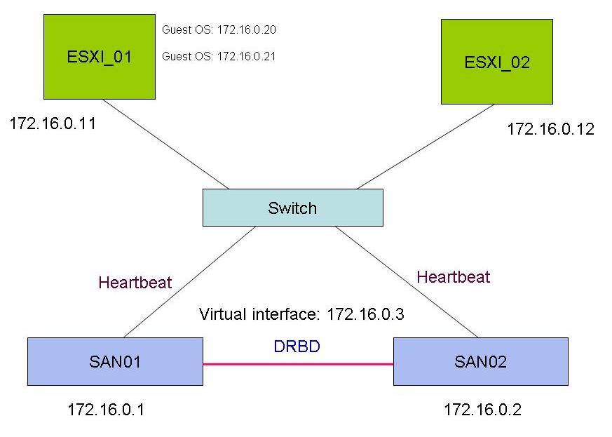
As an example I grabbed the picture on the right from a thread on the VMware community forum. In fact someone was trying to achieve exactly this using two opensource technologies: OpenFiler (to expose the storage to servers via iSCSI / NAS protocols) as well as DRBD (to keep the storage on the two servers in sync). The idea is that both ESX servers would connect to the 172.16.0.3 IP interface which in turns exposes storage via iSCSI / NAS protocols for the VMware cluster to use. Since the IP is virtual (i.e. can failover from one node to another - SAN01 or SAN02) and since both storage devices are kept in sync by means of the DRBD algorithms, you can implement a basically free storage-based replication solution for your Campus (granted you will NOT attach to a single Ethernet switch as per the picture!). Again, this architecture, as the others we have seen, is very prone to split brain type of scenarios. As an example, digging into the DRBD documentation on line I found out that they have a number of choices that can be configured when split brain events occur. You can find a brief formal description here.
For your convenience I will list hereafter the various options offered:
Discarding modifications made on the �younger� primary.
Discarding modifications made on the �older� primary.
Discarding modifications on the primary with fewer changes.
Graceful recovery from split brain if one host has had no intermediate changes.
Options #1, #2 and #3 would be very worrying as you may guess. Option #4 would be realistically impossible. In such a scenario, a better option would be to have DRBD stop the I/O operations so that a system administrator could determine the root cause (i.e. split brain or actual site failure). This will cause downtime and a manual activity (not really desirable in a Campus scenario per our description) but, at least, it ensures data consistency. On the other hand the recovery manual operations (as in the case of the NetApp MetroCluster) are easy to execute compared to more complex DR solutions.
On top of this remember we can't pretend that FC and IP-based solutions are equal in terms of performance, robustness, reliability. I am clearly not referring to the open-source solution above which cannot even be considered beyond a lab exercise (I would think twice before putting into a production shop something like this - no matter the size). I am referring to mid-range and high-end products from Tier 1 vendors: no matter what, the iSCSI and NAS protocols are not seen as of today as a replacement for Fibre Channel SANs and will not be seen as such any time soon. Especially for big enterprises that have invested so much in their FC infrastructure. This is not just a "legacy" discussion however: there are some enterprise characteristics in a FC SAN that cannot be matched by IP-based protocols.
Ensure you search through the VMware Hardware Compatibility List (HCL) to find out whether your iSCSI / NAS (and FC) solutions of choice are officially supported.
6 . 2 . 2 Campus Implementations for Microsoft Virtual Infrastructures
In this section, similarly to what we have done for VMware Virtual Infrastructures, we will cover both Host-based and Storage-based replication implementations to achieve the target Campus scenario. You'll notice that Microsoft Hyper-V will come out pretty flexible due to its nature (i.e. virtualization just as a role of a legacy OS). Expect Storage-based scenarios to be equivalent for the most parts (since the idea is to transparently present a stretched storage domain which is hypervisor agnostic). More below.
6 . 2 . 2 . 1 Campus Implementations for Microsoft Virtual Infrastructures (Host-based Replication)
What you could do with Microsoft is quite different than what you could do with VMware. Microsoft Hyper-V leverages a standard Windows 2008 installation in its "parent partition". This is far different than ESX and its Console OS (or ESXi where the Console OS doesn't even exist). While there are advantages and disadvantages in both approaches - which I am not touching in this document - there is a clear additional flexibility when it comes to host-based storage replication with Hyper-V since you can leverage an extensible and ecosystem-rich environment (i.e. the Windows 2008 Parent Partition).
As an example, you could technically use a Volume Manager at the Hyper-V host level to mirror two LUNs coming from two different storage devices. When I first looked into this it appeared immediately clear that you couldn't do it out-of-the-box with Windows 2008. We are obviously talking about a cluster of Windows 2008 servers (i.e. Microsoft Failover Cluster aka MSCS) and in this setup Microsoft doesn't support Dynamic Disks (only Basic Disks). And since Mirroring of two volumes is only available with Dynamic Disks this was not open for discussions. Having this said there is nothing that would prevent a third party ISV to inject a more flexible volume manager that is capable of doing that. Off the top of my head I can think about two of them:
Veritas (now Symantec) Volume Manager: this is the historical third party volume manager for Windows (as well as other platforms). We have briefly touched on it in the VMware section.
Sanbolic Melio File System / LaScala Volume Manager: this is one of the partners MS has been working hard lately to address the cluster file system issue (i.e. the issue is/was VMware had one, MS did not).
Melio is a cluster file system that allows Hyper-V hosts to manage many independent virtual machines per LUN. Microsoft has partially addressed this problem with Hyper-V R2 which now supports Cluster Shared Volumes. If you want to know more about CSV you can read this article. MelioFS is still a better choice for performance and scalability. Sanbolic also provides a Volume Manager called LaScala; at the time of this writing the mirroring capability -which is what we need to implement our host-based replication scenario - is not available but the functionality is on the roadmap (check with them for the latest).
The picture shows a potential Campus scenario using a third party volume manager. Should one of the two buildings/sites (with 1 Storage device + 2 servers) fail, the remaining part of the infrastructure would carry on the work. Consider that all servers have, in this particular case, access to all mirrored LUNs at the same time, thus providing a higher level of flexibility leveraging a cluster file system (be it Microsoft CSV or Sanbolic MelioFS depending on the solution you may want to implement).
Consider that this configuration is protocol agnostic but only works with block-level access (not file-level access). This is obviously due to the fact that a Volume Manager assumes access to a RAW LUNs and not a network mount point to an existing file system on the network. As a result of this SAS, FC and iSCSI storage devices would be all capable to implement something like this. This rules out the usage of NAS devices.
Coincidentally, other than the volume manager architectural discussion, Microsoft has decided so far not to support NAS (be it NFS or CIFS) based storage to host virtual machines in Hyper-V environments.
While in theory this architecture should be open enough to let you use your clustering software of choice (i.e. Veritas Cluster Server for example), Microsoft seems to be building most of the virtualization oriented functionalities (i.e. LiveMigration and QuickMigration for example) around their built-in clustering technology making it a de-facto must-have in virtualization scenarios.
There is an alternative technology that may allow you to achieve similar results in a Hyper-V context and that's Double-Take GeoCluster. It is a technology that allows you to stretch a Microsoft Failover Cluster (MSCS) leveraging two different storage servers replicated via software mechanisms. It's very similar to the other popular "stretched Failover Cluster" configuration that leverages Storage-based replication (this is discussed in the next section) and the only difference is that, instead of leveraging proprietary built-in storage algorithms, it leverages the Hyper-V hosts to send data (at the byte level) from the active server (and active storage) to the passive server (and passive storage).
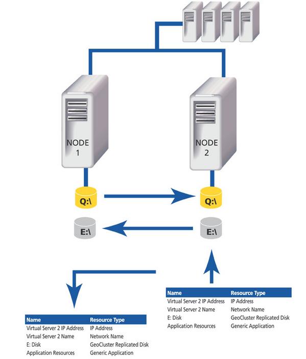
As you can depict from the picture (example) the Double-Take technology is responsible for keeping the drive Q:\ and E:\ in sync. In fact these are not shared disks (as it's often the case in cluster scenarios) but they are distinct set of disks coming from distinct storage servers (they may also be local hard drives installed physically in the nodes). In this example there are two virtual machines configured, one on the Q:\ drive (which is owned by Node 1 and replicated to the storage connected to Node 2) and the other virtual machine is on the E:\ drive (which is owned by Node 2 and replicated to the storage connected to Node 1). In case of a failover the VM gets moved to the other host and the active disk follows the VM.
Having this said, at the time of this writing, this solution only works without a clustered file system. As it is the case for Failover Cluster integration with Storage-based Replication, this solution does not work with CSV (or any other third party cluster file system).
I will update the document accordingly in the future, should these limitations be removed.
Being able to implement a Campus scenario using a host-based storage replication mechanism is very interesting. Not only it allows for storage device independency (although the level of official support when using heterogeneous storage devices might vary) but at a minimum it allows the usage of cheaper storage in the back-end. Sure one have to take into account the third party volume manager but, as a rule of thumb, this software costs usually less than what you would have to spend for a storage-based replication solution in a Campus scenario. Many SMB customers, where budget is not unlimited, might be attracted by a cheaper solution like this. Another point of attention for this solution is that you need to account for hosts resources to do the dirty replication job effectively stealing resources that could have been delivered to the Guest OS (leading to a potential slightly lower consolidation ratio).
6 . 2 . 2 . 2 Campus Implementations for Microsoft Virtual Infrastructures (Storage-based Replication)
Storage-based replication solutions are supposed to be software agnostic and transparent to the virtualization solution being used. In fact these solutions just create a physically distributed single logical view of your centralized storage.
Because of this what we have discussed for VMware in the "Campus Implementations for VMware Virtual Infrastructures (Storage-based Replication)" is also valid for Microsoft Virtual Infrastructures as well. The only exception / difference that you need to take into account is that MS Hyper-V doesn't support the NAS (NFS) protocol to host virtual machines. All other protocols, mechanisms and layouts are similar.
As a background, it's interesting to notice that some storage vendors have historically implemented a certain level of integration between the Microsoft native server high availability functionality (Microsoft Failover Cluster) and their Storage-based replication between two independent storage arrays. This is similar to the Double-Take GeoCluster integration we have mentioned in the section above.
The idea here is that storage devices implementing an Active/Passive LUN replication can be controlled by the Microsoft Failover Cluster events: imagine a stretched Microsoft cluster comprised of two servers with two storage devices in replica (by means of their hw functionalities). Server A would work against storage A supporting a business critical clusterized application. A failover of the application not only would move all the processes to the other host but it would also invert the storage replication settings. Simply put this integration is basically a resource DLL that gets registered into the Microsoft cluster engine and that fails over the LUN (i.e. it changes the direction of the replica) along with all the other resources within the Cluster Resource Group. The picture below should explain what happens when a system administrator forces a failover at the Microsoft Failover Clustering level (note the red arrows and the active/passive LUNs):
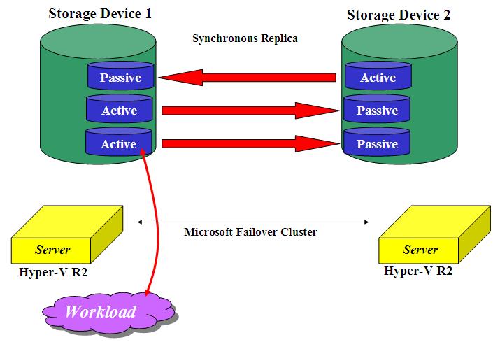
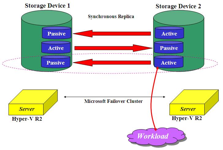
This level of integration works in a non-virtualized scenario (where the clusterized application is typically installed locally on each node and the LUN contains the persistent data the application needs to use). Official certifications aside it may also work in pre-Cluster Shared Volumes type of Hyper-V deployments where the LUN becomes the unit of failover along with the virtual machine(s) instantiated on that LUN (typically one VM but more VMs per LUN was an option too). Nowadays the usage of a Cluster File System (be it Microsoft own CSV or the Sanbolic MelioFS) breaks this architecture. In fact, generally with a Cluster File System, all Hyper-V hosts would have concurrent access to the LUN while maintaining the flexibility to spread the load of virtual machines across all hosts in the cluster. In this (advanced and desirable) scenario the unit of failover would become the VM as the File System remains concurrently shared across all hosts (this is true for simple Building scenarios where Storage-based replication is not being considered). At the time of this writing this solution (GeoCluster) is incompatible with Hyper-V R2 implementations that use a Clustered Shared Volume scenario (or any other cluster file system).
6 . 3 Globe Implementations
As per the Campus (aka Continuous Availability) scenario, the Globe implementation may be implemented using different technologies. As a reminder, Globe implementations are typically associated to long distances characteristics as well as semi-automated recovery procedures and with an RPO that is not 0 (actual RPO depends on the technologies being used).
6 . 3 . 1 Globe Implementations for VMware Virtual Infrastructures
Similarly to what happens in the Campus scenario, a Globe scenario accounts for two major implementations that are Host-based and Storage-based. Host-based, in this specific context, is used to describe DR type of solutions which are not based on native storage replication. Given the particular VMware hypervisor architecture, most often host-based solution are based on "external hosts" that implement the replica rather than the "ESX hosts" themselves.
6 . 3 . 1 . 1 Globe Implementations for VMware Virtual Infrastructures (Host-based Replication)
The overall idea of the Host-based Replication is that a third party entity ensures that, transparently and on-the-fly, the minidisk files of virtual machines in the production VMware infrastructure get replicated, by means of a standard TCP/IP network, onto the VMware hosts in the DR site. This is typically done taking regular snapshots of the VMDK file and sending the delta all the way to the DR site for them to be "committed" into the idle virtual machines. As you may guess, the RPO in a similar scenario is driven by the frequency you set for the snapshots. These products can usually be configured to take snapshots every few minutes but the reality is that most of these software are used to create DR solutions that have an RPO that varies between a few hours and a day (i.e. 24 hours). If this may sound high to you and not acceptable this is ok. Remember that for storage high availability and DR you don't choose a product and then complain about its unacceptable RPO. The idea is that you set your business requirements (i.e. RPO) and you then choose the product that satisfies it. If your RPO has to be in the range of seconds / minutes then most likely you will have to skip this section and look more into Storage-Based Replication for Globe solutions (next session). For the records, the advantage of Host-based Replication in the Globe scenario are similar to those we found in the Campus scenario: lower acquisition costs and more hardware independency.
There are a few products that I will list here as examples of this type of solution:
While each of the vendors will be willing to demonstrate you how better their own product is, in this context I will take the shortcut and will say that they are all similar in functionalities. The idea is to "connect" to a source VMware virtual infrastructure and to a destination VMware virtual infrastructure and implement two key things that are:
An algorithm to replicate the VMDK files across the "globe" (all the way to the DR destination data center).
A certain level of semi-automation to failover the production environment.
Point #2 is important and the word "automation" may be misleading. You don't want these solutions to auto-determine whether or not they need to failover. The idea of Globe (aka DR) solutions is that the trigger to initiate the failover procedures is left to the SysAdmin. This is different compared to Campus (aka Continuous Availability) scenarios where the idea is that the infrastructure responds automatically to critical events. This is the reason for which the products listed here implement point #2 by means of a so called red button that the administrator can push to initiate the actual failover. Check out the red button functionalities of all these products because each of them may provide different levels of automation: some products might implement a red button for each machine whereas others might implement a site-wise red button.
It is also important to note that we are not talking about a stretched cluster on multiple physical locations, as opposed to the Campus scenario we have discussed. We are talking about two loosely coupled datacenters each with its own "VMware identity". In a way you can assimilate this scenario as two independent Building implementations (i.e. two independent VMware clusters) tied together by a third party software that does #1 and #2 discussed above.
For those of you that think that a picture is worth 1.000 words this is an example of how the Veeam LAN-replication architecture looks like:
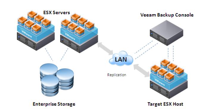
Double-Take for VMware Infrastructure and Vizioncore vReplicator have a similar architectural implementation. Note that I always talked about two separate data centers and logically separated clusters whereas in this picture the "recovery site" only shows up as a single ESX host with local drives. On one hand the picture is an oversimplification of a D/R architecture that could be far more complex (for example with a SAN at the recovery site). On the other hand it shows how these D/R techniques are flexible and adaptable to many circumstances (even the smallest).
It is important to remember that these products (and most of the other third party products that have similar functionalities) work with VMware-based software snapshots. Since they are storage agnostic they leverage the software implementation of snapshots that VMware has built into ESX. For this reason particular attention needs to be paid to the VMware infrastructure configuration. This ties back to the introduction at the very beginning of this document (Background: Storage Management Principles in a Virtual Environment). The usage of minidisks not only allows for more flexibility, generally speaking, but it is also the only configuration that supports VMware software snapshots.
This means that only VMFS partitions with VMDK files and RDMs in virtual compatibility mode are supported. RDMs in physical compatibility mode are not usually supported (as they cannot be used as a source for snapshots). This is one of the many reasons for which the usage of standard VMFS volumes and minidisks is so popular. As VMware introduced new Storage APIs for Data Protection with vSphere, some of the requirements and characteristics above may be changed.
As far as data consistency is concerned, these utilities are typically designed to interface Virtual Center which in turns call the VMware tools components to flush the OS cache before taking a snapshot. This ensures that the snapshot being sent to the DR site is consistent from an OS perspective but the same cannot be said for the applications running inside the virtual machines. In fact these applications (for example Microsoft SQL Server, Oracle Database, Microsoft Exchange etc) may be using their own memory caching mechanisms which are not integrated with the flush described.
At the time of this writing the VMware Tools do not integrated with additional software other than the operating systems so, at the recovery site, you will find your third party applications in a "crash consistent" state. Operating Systems delivered services would be in "quiesced" state though. Some of the vendors may provide a replication product that integrates better into the application stack which may result in better consistency state at the application level as well (they typically achieve this through Microsoft VSS integration or other application aware-techniques).
Additionally, being this solution an "abstraction" on top of an existing standalone VMware cluster (i.e. it doesn't integrate with any storage architecture), this means that it would work with any storage architecture with which the source (production) data center and destination (DR) data center have been built. This includes Fibre Channel, SAS, iSCSI and NAS type of technologies. Also, because of the agnostic storage architecture, you can use a mix of these technologies to implement the production and DR data centers.
6 . 3 . 1 . 2 Globe Implementations for VMware Virtual Infrastructures (Storage-based Replication)
This is VMware's bread and butter and where most VMware customers would be "defaulting" when talking about resilient storage designs. As you can see from the complexity of this document this is certainly not the only option available but it's certainly the most recurring during storage high availability discussions where the VMware platform is being considered.
The idea is similar to that described in the Host-based Replication section with the difference that the replica would be done by the native storage replication features rather than by an external third party software. This technique is not to be confused with the technologies we have explored in the Campus storage-replication scenario. The Globe scenario, by design, requires two independent and different sites (i.e. not a single stretched cluster); for this reason it is ok to have two independent storage domains (aka storage servers) replicating the data. See the discussion in the Campus Implementations for VMware Virtual Infrastructures (Storage-based Replication). Most - if not all - midrange and enterprise storage arrays in the market have this functionality available (typically, but not always, as an add-on cost). The idea is that the disks in the production datacenter are replicated through the proprietary storage replica algorithms onto a companion array at the DR site (typically the same model, almost always from the same vendor unless a certain level of storage virtualization is in place). Should the production site experience an outage, the storage at the DR site (in Read/Only mode during normal operations) is brought on-line for Read-Write mode and the local/independent cluster at the DR site is configured to read the now available LUNs and restart the workloads (i.e. the virtual machines). At first, it looks like an easy operation.
However, if you think thoroughly, you will appreciate that exporting & exposing storage-replicated VMFS volumes to a different cluster of hosts is not a trivial task. Similarly, restarting all VMs on the DR data center is not trivial either. In order to address all these challenges and make the administrator life easier during a failover event, VMware has created a product called Site Recovery Manager (SRM) to address this specific scenario. It is not the intent of this document to get into the details of what Site Recovery Manager does. This is a well known solution in the VMware community and this document is more intended to shed some light on the "unexplored" rather than reiterating the obvious and the well-known. However if you are new to this and want to get some insides about how it works you may appreciate this blog post of mine that I wrote to describe the manual steps to achieve all this as well as where VMware Site Recovery Manager ties in for such a scenario.
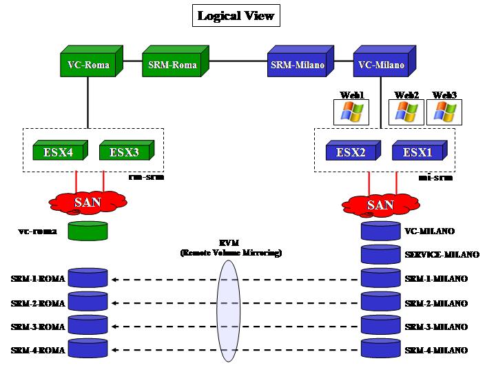
This is done using the LSI storage as the building block but it will provide you with a solid background of what happens no matter what storage (and proprietary replication) you use, be it LSI, EMC, HP or whatsoever. I am only attaching a couple of pictures from that document for those that are too lazy to check. They show the potential logical architecture and corresponding physical deployment:
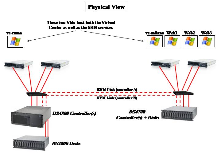
Note that, for the sake of simplicity, during the test we opted to host, on the same virtualized infrastructures, all of the components that are supposed to manage and protect them (i.e. the vCenter and SRM instances per each site). While we have done this because it was more practical for our tests, some customers may decide to implement these services on separated and dedicated hosts. This is a never ending debate in the community: should I host the management services on the same infrastructure they are managing? There is no definitive answer to that question.
A few additional things that is worth paying attention to: while the general idea is that there is a primary site and a DR site, note that SRM (and most storage replication algorithms) support bidirectional replication so that both data centers can have production workloads and can be configured to failover one over the other. This is why some customers are using these tools as a replacement for proper Campus solution in some circumstances. However, as we noted, this solution misses the key characteristics of a Campus solution (i.e. for example single stretched cluster and failover automation).
Another important aspect to keep in mind is that the current SRM release (4.0) does not support the failback process out of the box (one may argue that many customers do not have processes in place to support that either). While some storage vendors (such as EMC) have developed scripts that make the failback process a bit easier, the fact is that it's painful and not built-in into the (current release of the) product. This ties back to the positioning discussion we have done already. If you want to use this solution for real DR purposes it may make sense to see a failback process as a project of its own. I have been working with a customer, as an example, that didn't even consider a failback process and, in case of such a catastrophic event that would trigger a DR response, the DR data center would become the production datacenter indefinitely. At the time of this writing the official failback procedure is to reconfigure SRM and create DR plans that are the exact mirror copy of the original DR plans. In that case you can push the red button and trigger a so called "scheduled DR event". This will of course account for another downtime of the entire infrastructure (but at least this time can be scheduled).
In terms of protocols being supported, all storage vendors have products that have the replication functionalities we have described. Depending on the specific storage model some of the protocols may or may not be supported. In general, storage products with the described replication features have Fibre Channel and iSCSI protocol support. Some of the products may also have NFS support. None of them has SAS support. Also, some vendors may allow you to mix connection protocols in different data centers (for example Fibre Channel connections in the primary data center and iSCSI connections in the DR site).
6 . 3 . 2 Globe Implementations for Microsoft Virtual Infrastructures
Similarly to what we have described for VMware, there are - in theory - two philosophies for Globe implementations in a Microsoft Hyper-V context. The first one is Host-based and the second one is Storage-based.
The reality is that the Hyper-V ecosystem still needs to mature as far as DR type of solutions are concerned. Microsoft entered into this virtualization game late and only with Hyper-V R2 they have built a level of functionalities that make the product appealing for real life deployments. Obviously the initial focus is for standard deployments (the "Building" architectures if you follow my naming convention). You will have noticed that for the "Campus" architectures you can either leverage specific storage designs (which make the whole stretched configuration totally transparent to the hypervisor) or you can leverage the traditional Windows ecosystem for functionalities that were available before and can be used in a Hyper-V type of scenario (such as the Volume Manager technologies I have described); after all, being Hyper-V a Windows role has its positive side effects.
As far as "Globe" type of scenarios are concerned, the Hyper-V ecosystem still needs to mature and solidify although, for the reason we have just mentioned, there are traditional Windows-based DR technologies that can be potentially used out-of-the-box in Hyper-V scenarios.
6 . 3 . 3 . 1 Globe Implementations for Microsoft Virtual Infrastructures (Host-based Replication)
This is where Microsoft has the advantage of being able to leverage the existing Windows ecosystem to provide the same "experience" and features to Windows hosts that have been enabled with the Hyper-V role. Similarly to what we have described for VMware in the same scenario, the idea is that the replication of the guest operating systems happens via an external service (that may run on the virtualization host itself or on an external entity) instead of happening at the storage level via native replication. There are a certain number of tools that may be capable of implementing such a scenario but one of the most famous (especially in the Windows ecosystem) is Double-Take and specifically Double-Take for Hyper-V. We have already discussed what Double-Take for VMware Virtual Infrastructure can achieve and how it does it. Double-Take for Hyper-V is not different from a value proposition perspective although, obviously, the implementation details may vary. For example whereas The Double-Take for VMware version requires an external entity to interface the source and the destination hosts, Double-Take for Hyper-V gets installed on the Hyper-V parent partitions. Another big difference is that while Double-Take for VMware replicates changes leveraging VMware native software snapshots, Double-Take for Hyper-V replicates changes at the disk level without the need for Hyper-V snapshots.
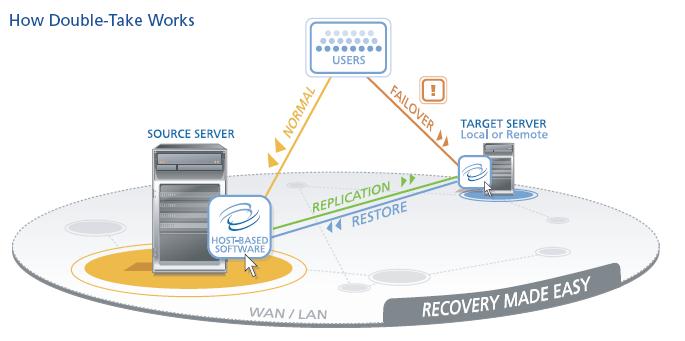
I haven't personally tried this myself. The documentation I have read so far doesn't mention whether this can be used in conjunction with Failover Clustering at the production location ( in scenarios where you may have, for example, 4 Hyper-V clustered servers in production and a couple of Hyper-V servers as target replication servers in a remote location, possibly clusterized as well). The documentation I have seen refers to integration with Hyper-V Manager not even Virtual Machine Manager / Failover Cluster Manager hence the doubt. Additionally it remains to be seen if, assuming it works with cluster setups, it also works with CSVs or third party cluster file systems. I will update this section as soon as I find more info on this.
Another implementation example of Host-based Replication for Globe scenarios where Hyper-V is the hypervisor of choice is the Veritas Storage Foundation. Specifically for Globe scenarios, it is worth mentioning that this suite of products includes a feature called Veritas Volume Replicator which allows to replicate a set of data (or a set of VHD files in this case) across an IP network (LAN or more specifically a WAN given the distance). The idea is similar to all of the Host-based Replication technologies we have seen so far. Veritas (now Symantec) typically offers this solution in conjunction with Veritas Cluster Server which includes a globally dispersed cluster option. While the Veritas Volume Manager we discussed in the Campus scenario for Hyper-V integrates well into the Microsoft Virtualization framework (i.e. Hyper-V, Virtual Machine Manager and Failover Clustering) the Veritas Volume Replicator product could possibly require other pieces of the Veritas offering (i.e. Veritas Cluster Server with Global Cluster support) which is incompatible with other Microsoft key components such as the Failover Clustering. Since Microsoft is hard coding most of the virtualization features (such as LiveMigration) with the Failover Cluster functionality, it may be impossible to get rid of this fundamental piece of the Microsoft architecture and replace it with something else. Still digging into it.
As it often happens for Host-based Replication solutions, the storage protocol is not a variable in these implementations so you can use either FC, iSCSI, NFS or SAS (or a mix of them) in the source and destination data centers.
6 . 3 . 3 . 2 Globe Implementations for Microsoft Virtual Infrastructures (Storage-based Replication)
This is where Microsoft is falling short. The Microsoft ecosystem for long distance DR scenarios is largely based, as of today, on Host-based Replication scenarios that we have discussed in the previous section. The only viable Storage-based Replication solution available for Windows is the Failover Clustering integration with selected vendors that implement Storage-based Replication technologies. We have briefly discussed this solution in the "Campus" scenario because its characteristics (RPO=0 via synchronous Storage-based Replication as well as automatic failover) make it look more like a technical implementation of a Campus / Business Continuity architecture. Having this said many still see this solution as a viable "Globe" implementation. I don't personally consider this a viable DR implementation for a number of reasons, certainly the most important of which is that you want to have a certain level of "human control and judgment" before you commit to a DR failover. This solution is instead fully automated since it leverages the standard Failover Clustering capabilities built into the Windows stack (and hence available to the Hyper-V role as well). For the records this solution can be tweaked for not failing over automatically should the use wish so. However, as we have already mentioned in the other section, at the time of this writing there is no possible integration between this "stretched Failover Clustering" configuration and Hyper-V R2 when used in conjunction with CSV or other clustered file systems technologies from third parties.
An approach that is more appealing (to me at least) to solve the DR issue in a Hyper-V context is what Citrix is releasing with their new Essentials package. At the time of this writing the new Citrix Essentials package for Hyper-V R2 seems to include a VMware SRM like feature called "Site Recovery with StorageLink". This is what the web page reports at the moment:
"Site Recovery uses StorageLink technology to unlock underlying storage array replication services, giving you the toolset you need to enable remote fail-over strategies for their Hyper-V environments. You can use StorageLink Site Recovery to set up native storage remote mirroring services, then test the recoverability of virtual infrastructure at remote sites through the staging capabilities included with Site Recovery. Instant clones of recovery VMs can be created and placed in isolated networks where you can test recovery without impacting ongoing data replication or access to critical Hyper-V infrastructure.
Additionally, you can use workflow orchestration tools in Citrix Essentials and Windows Server 2008 Clustering to build out a completely automated DR solution for your Hyper-V infrastructure."
And this is the picture which comes with the description:
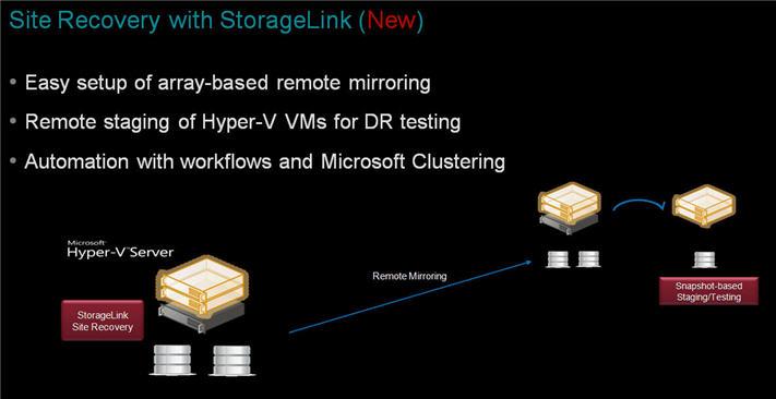
While the implementation of this product may end up to be vastly different than the VMware Site Recovery Manager, the philosophy behind it is pretty similar and it maps/fits more nicely the segmentation I have done in this document. I am assuming, reading what's available to date, that the "automation" Citrix is referring to is similar to the red button provided by VMware Site Recovery Manager. It's in fact important to distinguish between "automation" used to define an automatic and unattended action triggered by a given event and "automation" used to define a bundle of complex tasks coded and tied together in an atomic action, whose execution is dependent by a human trigger. The latter is what a real "Globe" (or DR) implementation should provide. Similarly I am assuming that the reference to the Microsoft Failover Clustering technologies is meant to describe the integration between these "DR rules" implemented at the Citrix Essentials package level and the local Failover Clustering technologies that can be used within the two "logically" separated clusters and data centers.
It remains to be seen whether the product in subject is a framework that can be programmed to create an SRM-like experience or whether it provides an SRM-like experience out-of-the-box.
Generally speaking we are at the very early stages of building effective DR solutions based on Hyper-V. This is true both from a product perspective as well as from a best practices perspective. This will inevitably change as time goes by and more and more customers look into this for their own implementations.
The storage protocols that can be implemented (FC, iSCSI, NFS) may vary based on specific storage models.
6 . 4 Conclusions
As I have said at the beginning the whole point of this document is to create a framework for you to think about your storage high availability plans. While the first part is more philosophical (subjective) the second part is more practical (objective). I invite the readers to send me feedbacks for both but specifically for the second part of the document. It's almost impossible to get everything right (as there are too many products and actual implementations to track). There are certain things that are not accurate because they have not yet been fully released. This is specifically a problem with third party solutions that might work with VMware VI3 / Microsoft Hyper-V but may not work with VMware vSphere / Microsoft Hyper-V R2 (or viceversa). I have tested many of the implementations listed myself (either in the lab or for customers). However, for other implementations, I have only read the documentation and I don't have practical hands-on experience. That's where your help, as an experienced end-user or a vendor (but please avoid flooding me with marketing/sales information about your products though), is appreciated to set the record straight in this document. Any feedback you may have please send me a private e-mail to massimo@it20.info.
Back to it20.info